Capacitive Touch Panel System Integration Guidelines

System Integration Guidelines for UICO projected capacitive touch panel products.
UICO touch screen experts are based in the United States. We provide design and egineering support from our home office in Illinois. There are many considerations when integrating into a new system. Below we have outlined some of the more important factors to consider such as:
-
Screen Orientation
-
Touchscreen Tilt and Mounting Angle
-
Screen Bezel Shape, Size and Material
-
Cover Lense Thickness
-
Film and Chemical Coatings
-
Thermal Management Considerations
-
LCD Bonding and Mechanical Support
-
Touch Controller Location
-
Touch Sensor Proximity to Other Devices
-
Cable Routing
-
Grounding Considerations
-
Power Supply Options
-
Bonding the Cover Lense and the LCD Touchscreen
-
Storage
-
Handling and Cleaning

Screen Orientation
The screen orientation (landscape or portrait) can drive several important design decisions. If an LCD will be bonded to the touchscreen, the aspect ratio and orientation can play an important role in the LCD selection.
-
The location of LCD mounting features and cabling should be considered early in the mechanical design of the touchscreen assembly.
-
Viewing angles and perceived brightness may be different between portrait and landscape mode for some LCD displays, and LCDs with polarizing filters might not be viewable with polarized sunglasses in the wrong orientation.
-
In portrait mode, an onscreen virtual keyboard will have smaller buttons and may require greater touch accuracy/resolution, resulting in reduced glove performance for thicker gloves.

Touchscreen Tilt and Mounting Angle
-
Water will shed from the touchscreen more easily when vertically mounted, resulting in the best water immunity.
-
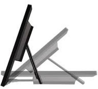
A mounting angle of less than 45° can result in large drips and streaks that may cause false touch events.
-
A horizontally mounted screen can pool water, which will reduce the overall touch sensitivity of the screen.
-
For any mounting angle, a hydrophobic coating is highly recommended for best water performance.
-
Fully test and qualify displays that may contain conductive brightness enhancement films. These films may shift inside the display when tilted and interfere with touch performance during operation.
The tilt or mounting angle of the touchscreen should be considered when water immunity is required.

Screen Bezel Shape, Size and Material
The shape of the bezel surrounding the touchscreen should be considered when water immunity is required. A conductive bezel can reduce touch performance around the edges of the touchscreen in some cases.
-
A vertical flush mounted touchscreen is best for applications where water needs to easily drain off the screen.
-
A shallow recess of a few millimeters for the touchscreen may result in a water meniscus forming and clinging to the edges of the screen, and a larger protruding bezel can allow water to become trapped and pool at the bottom of the screen.
-
When water accumulates at the edge of the screen, there is an increased chance of false touch events and a general loss of touch sensitivity.
-
A conductive bezel ( metal or metalized plastic ) can attenuate the response of the electrodes at the edges of the touchscreen, leading to suboptimal dry and water performance.

Cover Lense Thickness
The cover lens thickness directly affects the sensitivity and accuracy of the touchscreen.
-
A thicker cover lens is recommended for applications that require protection from impact or rough handling, however a reduction in touch sensitivity and accuracy may occur.
-
A thinner cover lens is recommended for applications that require the use of thick gloves or a higher touch resolution, for example when using onscreen virtual keyboards with small keys on a small screen.
-
A higher touchscreen controller voltage (5.0 – 5.5 V) should be used when a thicker cover lens is required to help optimize the performance.
.jpg)
Film and Chemical Coatings
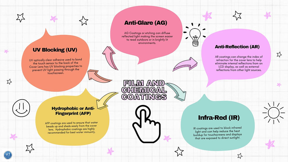
A variety of screen coatings or etching can be used to help reduce glare, improve sunlight readability, and improve water touch performance.

Thermal Management Considerations
Thermal protection and dissipation options should be carefully considered when using a touchscreen and display in an outdoor enclosure.
-
An outdoor touchscreen typically uses a high brightness LCD display which can generate a lot of heat. Additional power supplies and electronics in the same enclosure will add to the heating. In direct sunlight or a hot ambient environment, a sealed enclosure can become heated beyond the rating for the display, electronics, adhesives, or plastics used in the construction.
-
Passive or Active cooling should be considered to help manage the buildup of heat in assemblies or subassemblies that may experience thermal extremes. This can include air vents, heatsinks, thermoelectric cooling, and fans.
-
An IR blocking coating can be applied to the cover lens for products that will be exposed to direct sunlight. The coating will help reduce the amount of infrared light that shines into the touchscreen assembly, helping to keep the assembly cooler.

LCD Bonding & Mechanical Support
There are several options for bonding an LCD display, touchscreen, and cover lens. Mounting the resulting assembly into an enclosure should be carefully considered. An optical bond is not intended for mechanical support of an LCD display.
-
Larger or heavier LCD displays should be supported using strong mechanical mounts such as screws and brackets.
-
Glues or adhesives that are used to mechanically support the LCD must be carefully selected to support the weight, shear, and tensile forces over the full temperature range of the assembly.
-
An optical bond between the touchscreen and LCD display cannot be used to support the weight of the display. Any mechanical stress on the optical bond may result in bubbles, migration, or delamination.

Touch Controller Location
-
The touch sensor controller board (FPC) can be located on any edge of the touchscreen for dry applications.
-
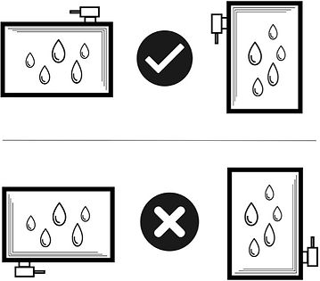
For water immunity applications, it is important that water flows away from the connecting electrode traces and the controller board. The electrode traces travel along the two edges of the sensor that are closest to the controller board.
-
If water accumulates on or near the connecting traces, a loss in sensitivity or false touches can occur.
Ensure that the touch sensor controller board is secured to a stable surface. For water immunity applications, the touch sensor controller board should be mounted towards the top of the sensor.

Touch Sensor Proximity to Other Devices
Peripherals near the touchscreen may cause interference, depending on distance, frequency, and signal strength. Custom algorithms, tuning, or shielding can often be developed to help minimize the impact. Contact UICO for a risk assessment.
-
Any device with an RF antenna, including AM/FM radios, cellular, WIFI, Bluetooth, or NFC systems should be reviewed and tested.
-
Any device with a strong electrostatic or electromagnetic source, such as wireless chargers, card readers/writers, switching supplies, backlight inverters, or transformers should be reviewed and tested.
-
Any device with moving metallic or magnetic parts, such as printers, motors, electromagnets, solenoids, relays, or other motorized hardware should be reviewed and tested.
-
Any metallic or magnetic device that vibrates, such as haptic systems, buzzers, or speakers should be reviewed and tested.
-
Remove the protective cling liner before testing touch. The liner will create static performance issues and ghost touch

Cable Routing Considerations
-
LCD LVDS and LCD backlight cables, power, I2C, USB, and any other communications cables should be routed away from the touch controller and flex circuit.
-
Cables that are near the touch controller or flex should be shielded whenever possible. Grounded foil tape can be used to cover unshielded cables if needed.
-
If cables need to cross, keep them perpendicular. Parallel routed cables are more likely to interfere with each other.
-
The cable routing and any resulting signal interference can affect the touchscreen tuning. Changing the cable routing or shielding may require retuning the touch sensor.
-
Cables from other devices and peripherals can cause interference and should be kept at a safe distance from the touchscreen controller and flex circuit.


Cable Flex Tail Routing
-
Do not crease or fold the touch screen flex tail as this can cause damage due to trace cracking
-
Insulate metal that is in contact with the tail
-
Do not pinch or crimp the tail between metal frame joints
-
Avoid any mechanical stress applied to the tail in the integration as this can create failures
Examples of creased and pinched tail damage above.

Proper Grounding
Proper circuit grounding of the touch controller and surrounding metalwork is critical.
-
The touch controller requires a short low impedance ground path to the host circuit and LCD driver circuit.
-
A short impedance ground path is also required between the touch controller and any surrounding metalwork, including the LCD backplate and device chassis. Circuit ground and chassis ground in view of the touch sensor needs to be at the same potential to avoid excessive signal noise.
-
Ground connections that use dissimilar metals must be designed carefully to avoid galvanic corrosion, especially in high humidity applications.
-
If a conductive adhesive such as foil tape is used as a ground connection, ensure that the adhesive is compatible with the thermal and humidity requirements for the application.
-
High vibration applications may require additional grounding reinforcement and design considerations. Consider mechanical ring-lug connections.
Integration Grounding Concerns:
-
Avoid using tapes over the top of the controller to mechanically create a conductive contact the LCD metal backer. This is not an ideal solution.
-
Poor grounding designs create intermittent ties to ground, resulting in unpredictable touch performance issues.
-
Verify there is a solid conductive contact to ground when using paint-lock or powder coated type metal frames. The paint acts as an insulator that can prevent proper conductive connections with ground.
-
If performance issues are present, verify electrical noise is not coupling with the ground connection of the power supply.

Power Supply
The touchscreen requires a clean and stable power source for best performance.
-
A dedicated precision LDO (low dropout) linear regulator is highly recommended.
-
Most UICO touchscreens can be powered over a range of voltages. Typically, the higher the voltage, the better the touch performance.
-
For best glove performance, or for a thick cover lens, 5V to 5.5V is recommended.
-
The touch sensor voltage source should remain stable and independent of other load changes from the host, for example from speakers, motors, lighting, printers, or other peripherals.

Bonding of the Cover Lense and LCD
-
Use high quality optical type adhesives for bonding, not structural adhesive.
-
Avoid any tensile, compressive, or torque forces that can cause strain and optical deformation of the touchscreen to cover lens bond, or the touchscreen to display adhesive bond. Prolonged exposure to strain or uneven forces will cause delamination or failure of the optical bonding.
-
The cover lens must not touch the LCD surface during maximum bend.
-
Silicone OCA is recommended for outdoor applications to reduce UV-related yellowing and provide a more robust bond.
-
Consult with UICO during display selection. We may recommend an ITO GND plane on the back side of the touch substrate to minimize the impact of display interference, after a review of the build options and analysis of the signal noise.

Touchscreen Storage
Touchscreens need to be properly stored prior to assembly.
-
Store within specified temperature and humidity range, per the specification created for your touchscreen.
-
Store in the original packaging until ready to be installed.
-
Touchscreens must be kept standing up via PC board rack holder and can be stood up on their edge.
-
Avoid storing the touchscreen assembly in direct sunlight.

Touchscreen Handling
Handle the touchscreen with care to ensure no damage to the hardware.
-
Wear gloves when handling the touchscreen in order to prevent fingerprints or stains.
-
Do not hold or pull the touchscreen out of the box by the tail.
-
Do not place or rest any object or material on top of the touchscreen and do not stack touchscreens on top of one another.
-
Do not remove the protective liners on the touchscreen until you are ready to assemble them.
-
Use antistatic worksurfaces and wrist straps when handling the touchscreen to avoid ESD damage.

Touchscreen Cleaning
-
Apply Isopropyl alcohol (50:50 solution with water) to a clean, dry, soft, lint-free cloth for cleaning. Do not spray the Isopropyl directly onto the touch screen. Clean with a gentle linear motion across the length of the cover lens. Do not clean the cover lens with paper products or other abrasives cloths.
-
Do not clean the raw touchscreen (without cover lens) using any mechanical motion. Use ionized air to blow any debris off the front or back of the raw touchscreen.
-
Do not rub anything corrosive on the flex circuit.
-
Do not use any spray chemicals on or near a bonded touchscreen. Chemicals can soak into optical bond causing hazing, distortion, or discoloration.


